Fusion 360 Make Parts Browser Transpearant Again
How to convert an STL mesh to a Solid in Fusion 360
Fusion 360 is very popular among hobbyist and students who bask 3D printing. If you lot're wondering how to turn an STL file into a solid body, so y'all're in the right identify.
Before nosotros become started with actually converting the mesh model I want to cover some of the terminologies to ensure we're on the aforementioned folio, and so y'all really understand why we're converting the model.
(Click here if you lot prefer to larn by video)
The Mesh (STL) File
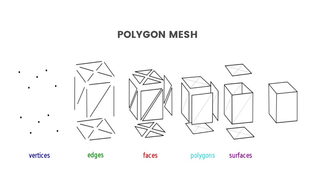
If you're familiar with 3D press and you lot use .STL files or .OBJ files then yous piece of work with mesh files all the time. A mesh file is a collection of vertices, edges, and faces that define a 3D dimensional shape. This great image from Wikipedia breaks downwardly how a mesh is congenital. Y'all'll encounter that it shows that mesh files are created with vertices, edges, and faces, which all create the polygon sides or surfaces of the object.
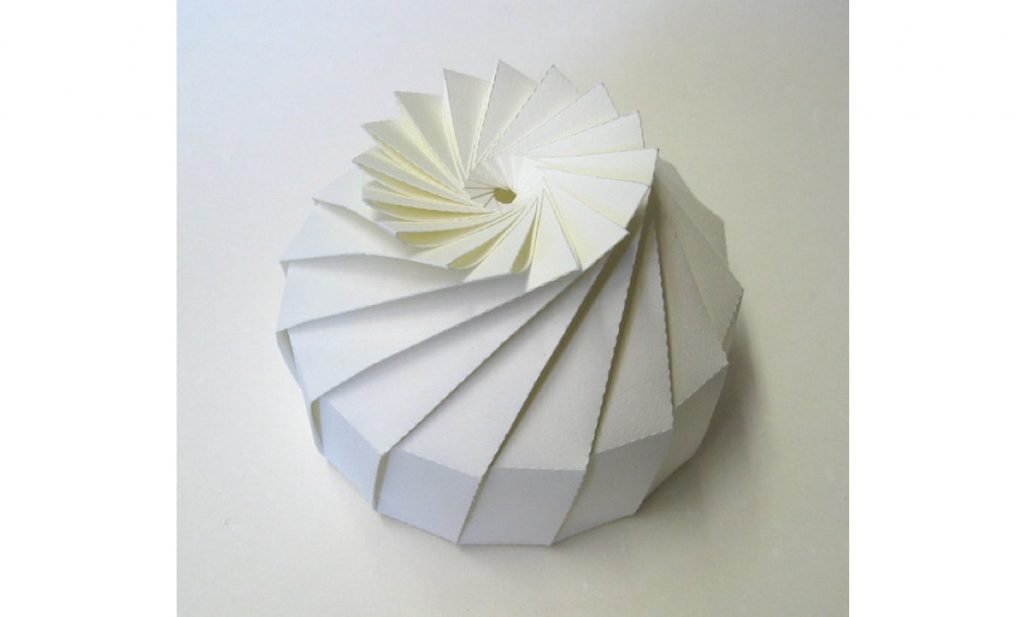
Ane of the most important things to know about meshes is that they are surface models. Now to assistance y'all grasp this concept nosotros can compare it to existent-life Origami. If we await at Re-arranges screen to wait at selected object. More than this object made out of newspaper nosotros encounter all of the different surfaces that make up this overall shape. Yet, the object is still hollow on the inside, as its solely made up of surface geometry.
STL vs OBJ Files
At present real quick let'southward take a look at the difference between the ii most common types of meshes, which are .STL and an .OBJ files.
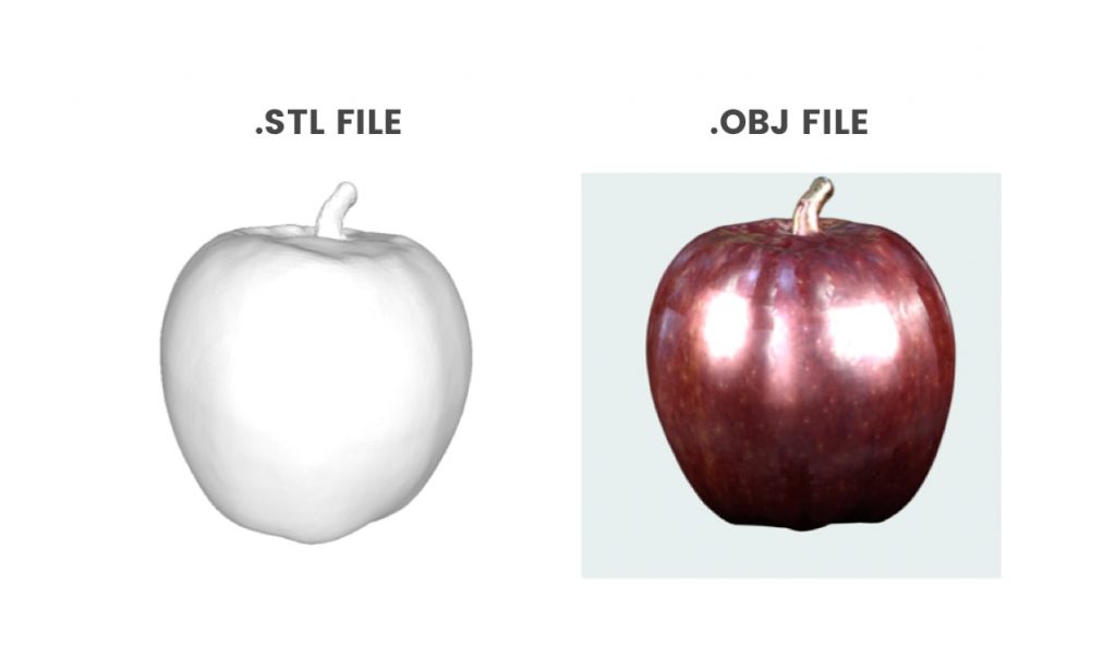
An STL file is the native file format for stereolithography and information technology's oft referred to as the acronym that represents "Standard Triangle Language" OR "Standard Tessellation Language." Put simply, an STL file is a type of mesh file created with unstructured triangular surfaces. Once more, it's just making upwardly the outer surface of the model and its Non a completely solid object.
On the other hand, we take .OBJ files. The but departure between an .STL file and a .OBJ file is that the .OBJ file displays some extra data on the surface. Then y'all'll see that .STL files are always gray, whereas .OBJ files can contain colour and texture data, which are displayed on the surface. The color and texture map are almost commonly captured by 3D scanners, which is why most 3D scanners are going to output your .OBJ file.
Now the last term that you'll need to understand here before I walk through the steps to convert an STL to a solid body is the term "BREP." Now, BREP stands for boundary representation and tin can be seen as the opposite of our mesh files, as it's a completely solid and watertight model. A BREP file is made upwards of topological and geometric information.
Alrighty, so now that y'all're familiar with some of the common terminology allow'southward take a look at how to use Fusion 360 to catechumen an .STL mesh file to a BREP solid trunk.
Mesh Workspace
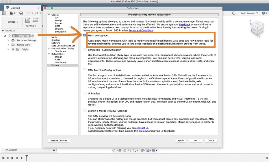
The first thing we'll want to do is make certain that the mesh workspace is enabled. To practice this select The selection manner controls how objects are select when yous drag in the canvas. More the preferences menu from the profile dropdown list and and so select "preview" and yous'll run across that you lot can toggle the mesh workspace on and off by clicking the checkbox. Now later on clicking the checkbox, you'll have to hit the apply push and and so the okay button.
1. Insert Mesh (.STL) File into Fusion 360
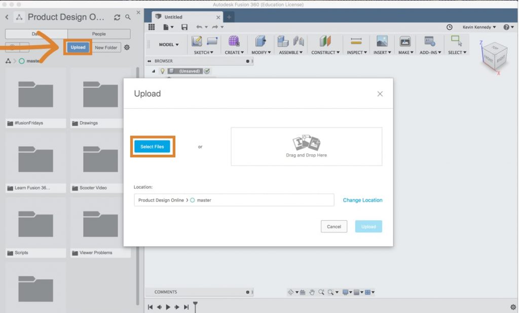
Now a lot of Fusion 360 users get .stl files from Thingiverse.com and they desire to modify them to fit (keyboard shortcut "f6") Makes the current file fill up the screen. More their own needs or they but want to customize them with their name or logo. For this demo, I'm going to use this downloaded phone stand Thingiverse file. The first thing yous'll have to do is import it into Fusion 360. There are two ways that you lot can import a mesh file into Fusion 360. The showtime manner would be to open up the information panel Opening The Information Panel gives you admission to your Project Files and Folders. Click the Show Data Console button in the upper left of the Fusion window. The Panel volition expand on the left side and display the projection folders. Y'all can as well add together members to projects and Import information from other sources. More and click the blue upload push. And then, If you select the file y'all can upload information technology. In one case the file has been successfully uploaded, double-click on the file to open it.
Note: Click here for the phone stand up STL file used in this demo.
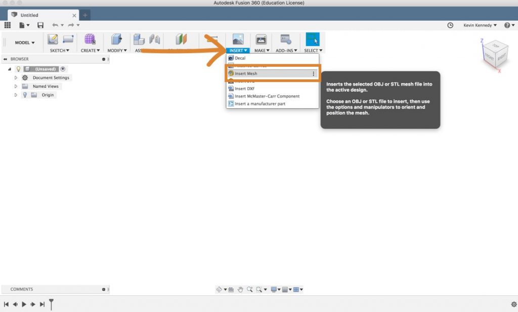
The 2nd way to insert a mesh file is to simply go to the insert menu. Select " insert mesh Inserts the selected OBJ or STL mesh file into the agile design. Choose an OBJ or STL file to insert, so apply the options and manipulators to orient and position the mesh. More " from the dropdown list. Then get ahead and select the file. Yous'll meet that before you tin work on the file it allows you to alter the orientation.
two. Irresolute Orientation of a Mesh File in Fusion 360
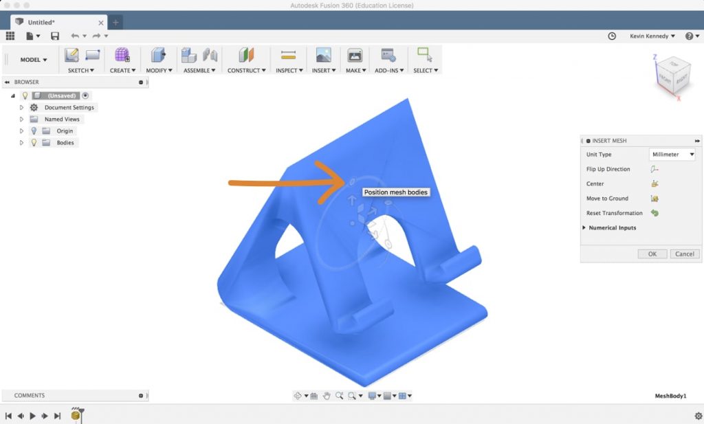
If I wanted the top of the phone stand to be the top of my orientation in the viewcube Utilise the ViewCube to orbit your design or view the design from standard view positions. More I could either drag the sliders around or I could select the "flip-up direction" in the insert mesh dialogue box Creates a solid box. Select a airplane, draw a rectangle and then specify the height of the box. More . You can as well hit "center" to motility it to the middle origin. If your file is floating in space for some reason, you can hit "motion to ground" to move it to the XZ or XY plane, depending on how your orientation is set. Lastly, be sure to click "okay" to confirm whatever orientation changes that you've made.
If y'all go to the workspaces card and still can't see the Mesh Workspace, it'due south probable because of the design history. You'll have to plough off the blueprint history by right-clicking on the file in the browser The browser lists objects in your design (everything from planes and sketches to parts and assemblies). Use the browser to make changes to objects and control visibility of objects. More and select "Do Not Capture Design History" and click the go along push to confirm. Now if you get back to the workspace selection menu you lot'll see that you tin can alter to the Mesh Workspace.
At this point Creates a sketch indicate. More , I also recommend irresolute the visual style so it's a bit easier to see all the triangles that make up the mesh. Nether the display settings Change display settings including the visual fashion, mesh display, surroundings, effects, object visibility, camera perspective, and ground planes. More select "visual manner," and then select "shaded with visible edges only." You'll encounter that if you zoom Zooms in and out every bit the mouse is moved from left to right. More in you can now see all of the vertices, edges, and faces that make up the mesh model (like I discussed in a higher place).
3. Converting the Mesh to Brep
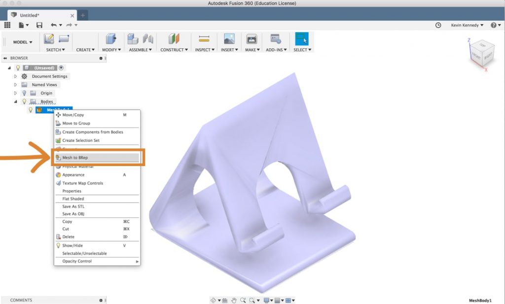
What confuses A LOT of Fusion 360 users is that yous'll actually need to be back in the Model Workspace Creates mechanical designs that contain mostly prismatic geometry. Access commands to create solid bodies. More than in society to convert a model. Select the Model Workspace and then to convert the mesh to a solid body all you lot'll have to do is correct click on the mesh and select "Mesh to BRep." Y'all'll then run across in the dialogue box that yous tin have it create a new body or a new component Creates a new empty component or converts existing bodies to components. When creating an empty component, enter a name and select the parent. When converting bodies, select the bodies to convert. More .
4. As well Many Facets (Triangles) Error
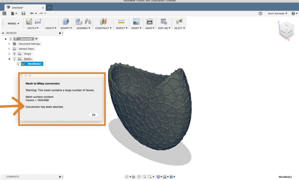
If you imported a fairly circuitous model and then it's likely y'all'll get an error bulletin at this point stating that there are too many facets or the number of faces for Fusion 360 to convert the model. In this pictured example here it looks like information technology has a little over 1.5 1000000 faces… and Fusion 360 tin really but compute approximately 50,000 facets. So before converting you'll beginning accept to reduce the number of facets.
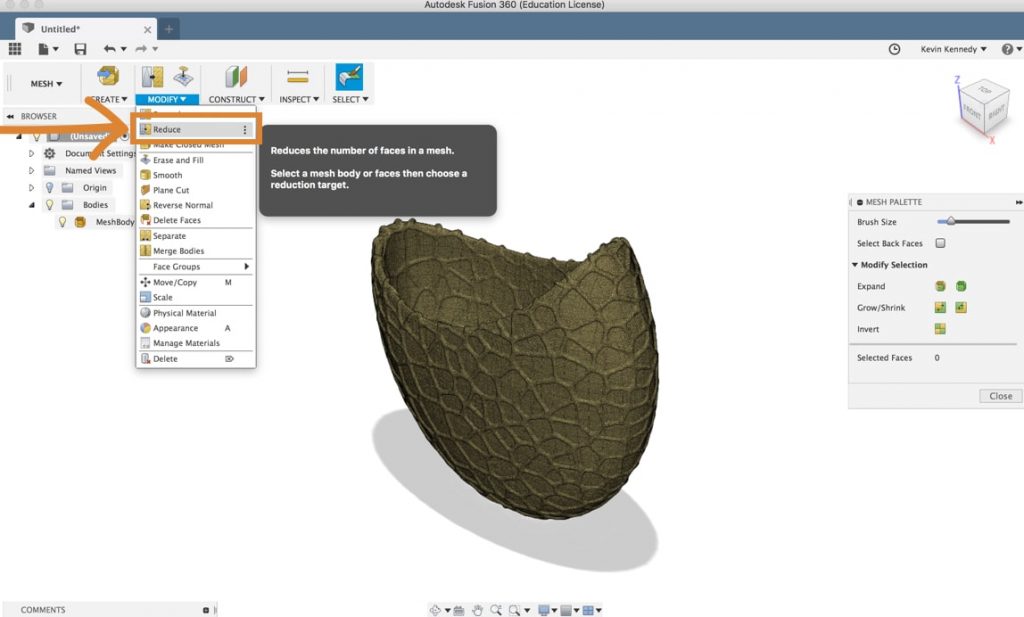
To reduce the number of faces yous'll accept to switch to the mesh workspace and then you tin can select "reduce" from the modify dropdown listing. Now nosotros'll start take to select the mesh faces or a body. So in some scenarios, you'll want to select merely a certain surface area of faces and in others, we'll desire to get alee and just select the entire torso from the Fusion 360 browser. The next option yous'll see is the reduced type. Adaptive means that Fusion volition adapt the surface triangles how information technology best fits the shapes or compatible volition force them to all be compatible in shape and size. Then for this circuitous object, I'll go out information technology set to adaptive and so it doesn't totally skew the overall shape.
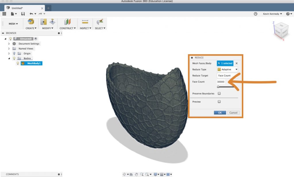
Now y'all'll want to reduce the number of faces so you lot'll have to select "face count" for the "reduce target." Then, for the number of faces, yous'll have to have this nether 50,000.
Notation: Information technology'due south a practiced idea to aim much lower than 50k faces as the more faces your model has, the more data Fusion 360 has to process. And so your file volition be much slower if yous're close to 50k faces.
After your model has re-processed and reduced the number of faces, you'll run across that if you switch back to the model workspace yous can correct click on the mesh and select "Mesh to BRep." Your model should catechumen at this point, but you may get some other alert if there are still a lot of faces which may tedious down the file quite a fleck. Personally, I always recommend reducing the face count as much as you tin without destroying your overall shape.
five. Cleaning Up Faces of an STL File in Fusion 360
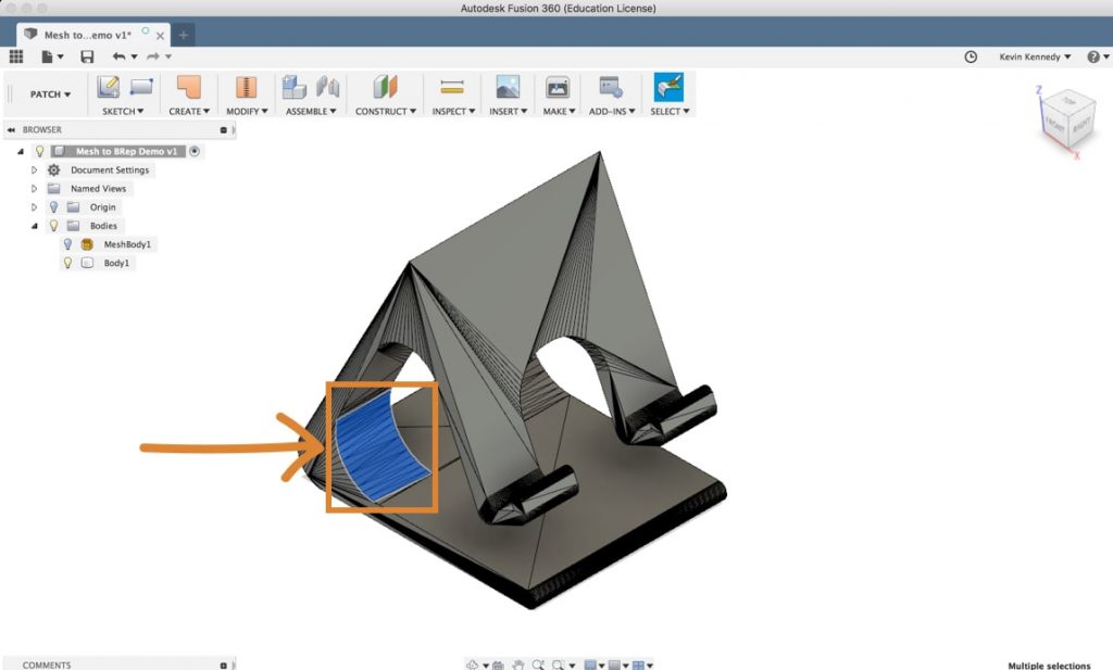
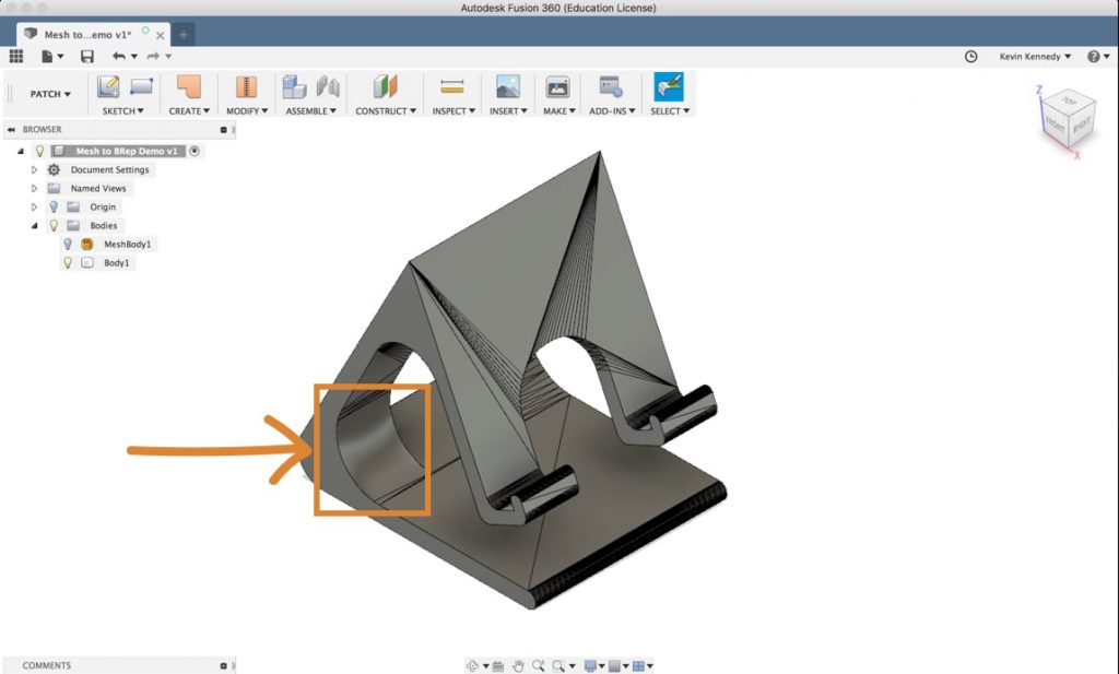
Now Fusion 360 did a pretty practiced job of processing this file and turning it into a solid body, but you'll see hither in the movie that there are still A LOT of triangular surface faces that make up the solid body. Sometimes these faces tin make it the way of altering the pattern to your specific needs. One thing yous can do is reduce the number of faces by merging them together.
At this point, you could zoom in and select all of the faces one by one, but an easier way would be to use the paint selection (keyboard shortcut "three") Choice by mouse downwards drag over targets. More tool. The paint pick tool is going to permit y'all to click with your mouse and elevate over all these faces to select them much faster. Earlier using the paint selection you lot'll want to set the selection priority to " select face priority Sets option priority to faces. Click to select only faces in the model. Click again to remove priority and allow selection of all objects. More than " which will help ensure that you don't select the entire component. If you go dorsum upwards to the menu and look at the selection filters you lot'll encounter that y'all can see that activating the "select face priority" characteristic turned all these other options off and only left the "body faces" turned on (which will help y'all select only the faces).
Now with the pigment selection activated you can click and drag beyond a number of faces. If you miss any faces you'll only concur down the shift key and select them.
Then, switch to the patch workspace and select "merge" from the change dropdown list. And you'll see that you can continue to select and merge faces to really make clean up this solid body model then it doesn't take and so many faces.
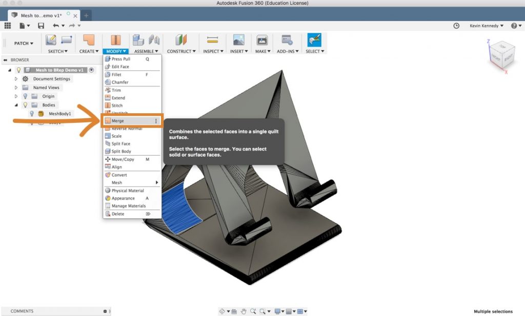
Having fewer faces will actually allow you to focus on the tools in the model workspace and won't restrict you as much as yous try to modify your new solid torso.
Prefer video over help articles?
Source: https://productdesignonline.com/tips-and-tricks/how-to-convert-an-stl-mesh-to-a-solid-in-fusion-360/
0 Response to "Fusion 360 Make Parts Browser Transpearant Again"
Post a Comment